Synchronized Flasher System for Enhanced Safety in Dangerous Curved Road Zones
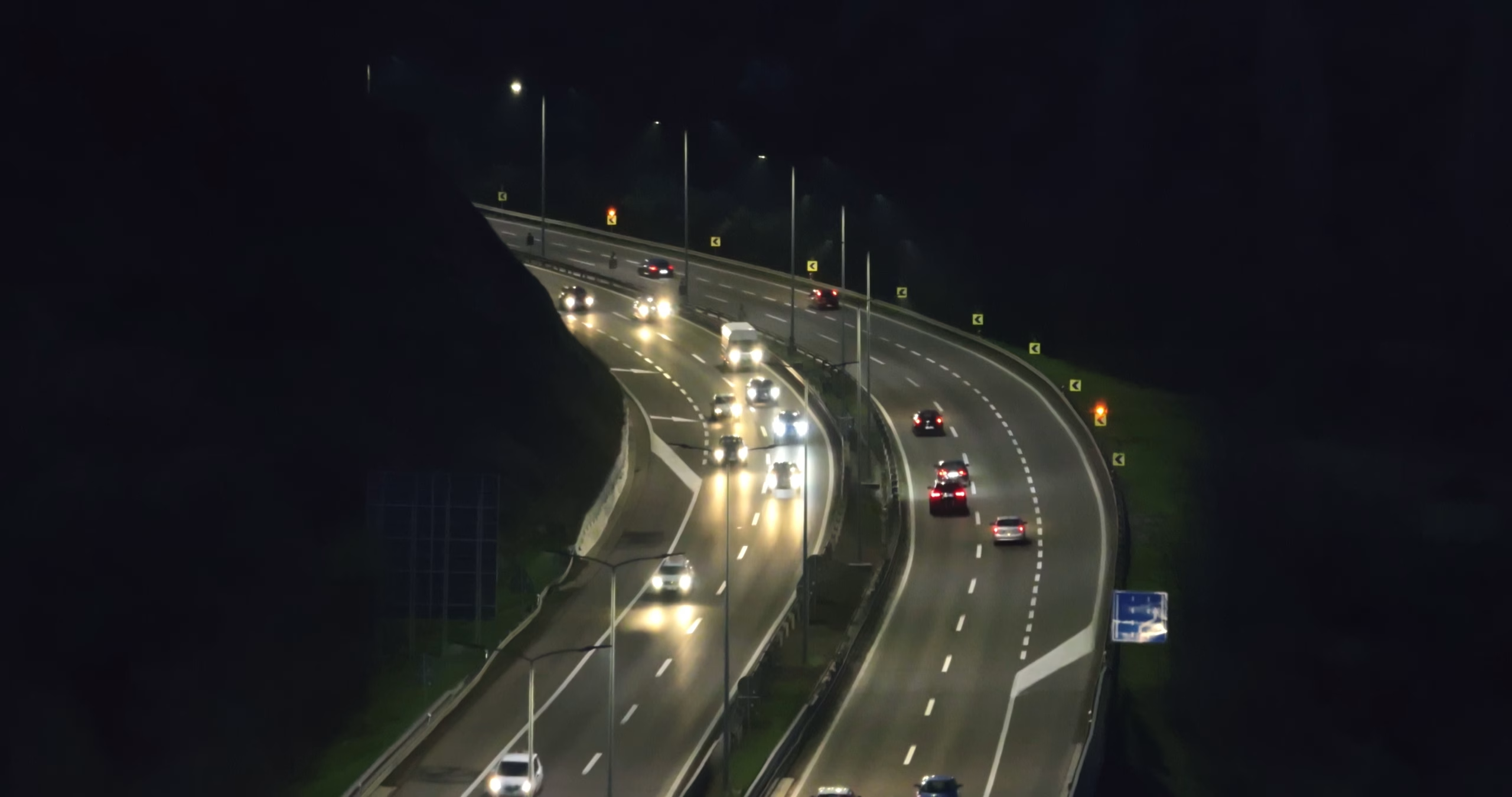
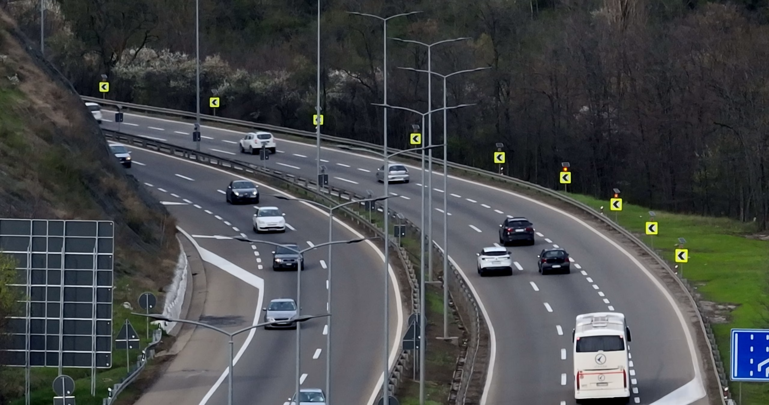
Synchronized flasher system for enhanced safety in dangerous curved road zones timely informs drivers that they are approaching a dangerous curve and should adjust their speed. The system’s effects on drivers are most noticeable in conditions of reduced visibility, such as fog, heavy rain, snowfall, and nighttime, as it helps them recognize the direction, length, and shape of the curve.
Elements of the warning system for dangerous curves with synchronized flashers:
- Control Unit CB-SST
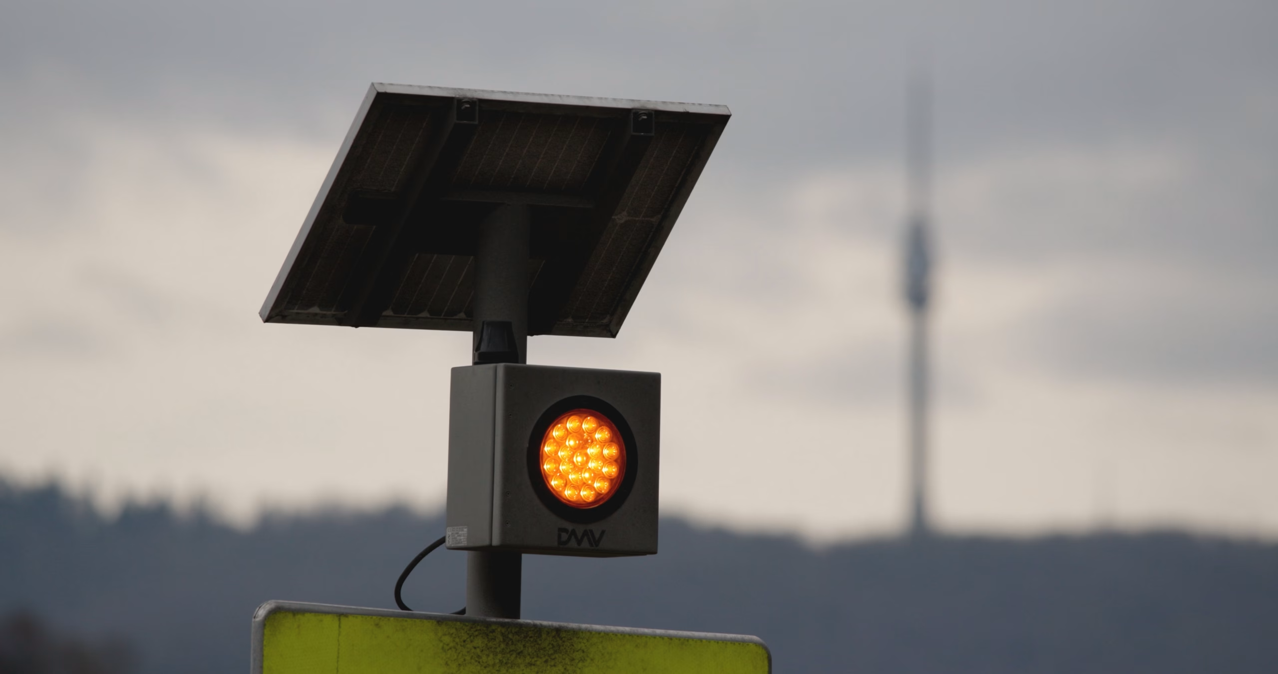
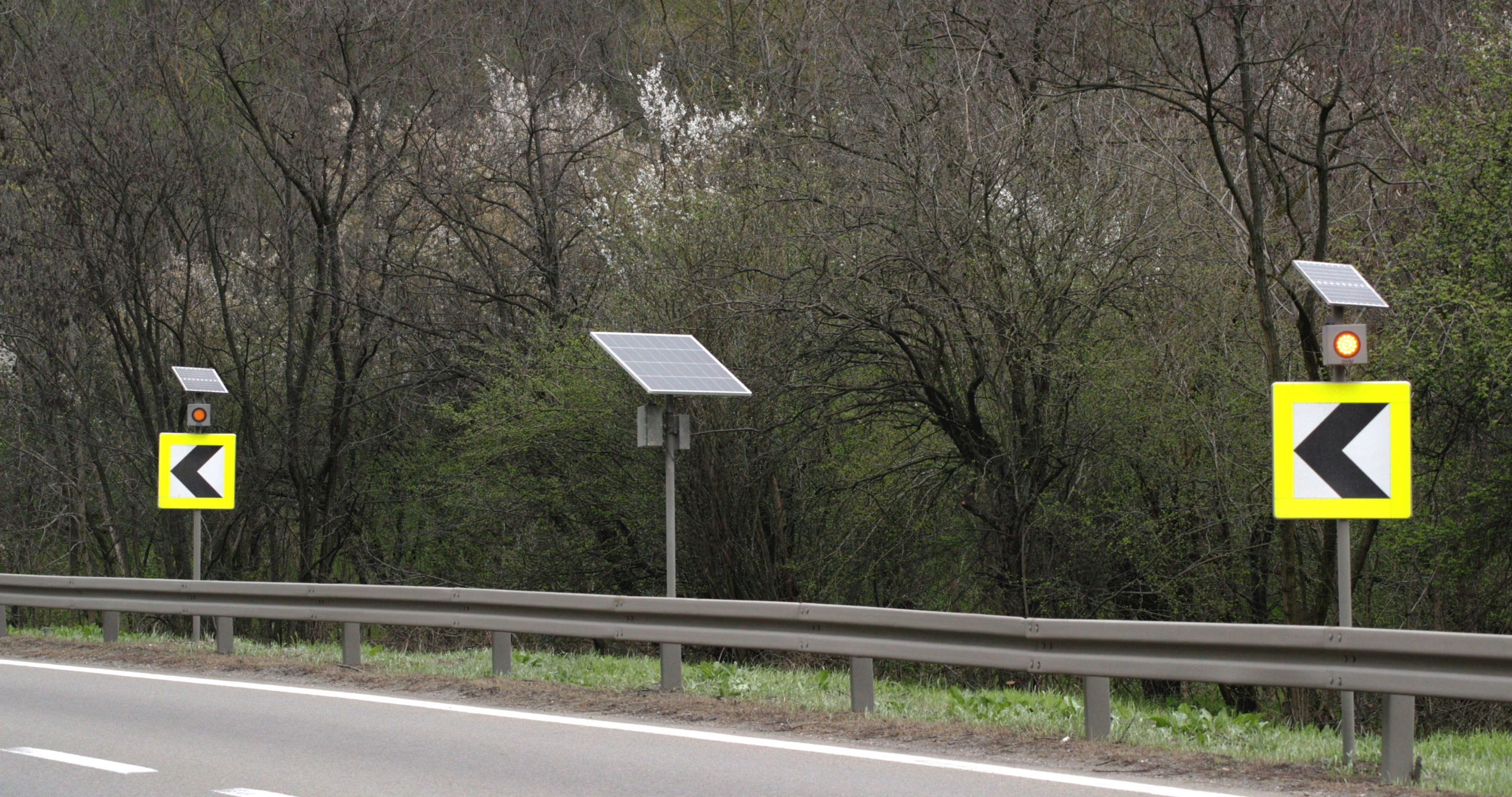
- Flashers
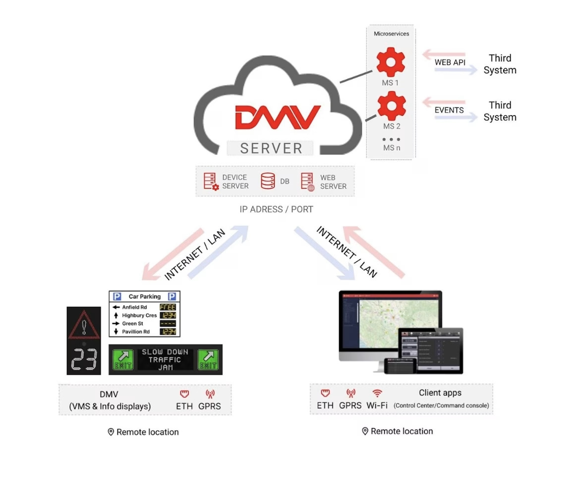
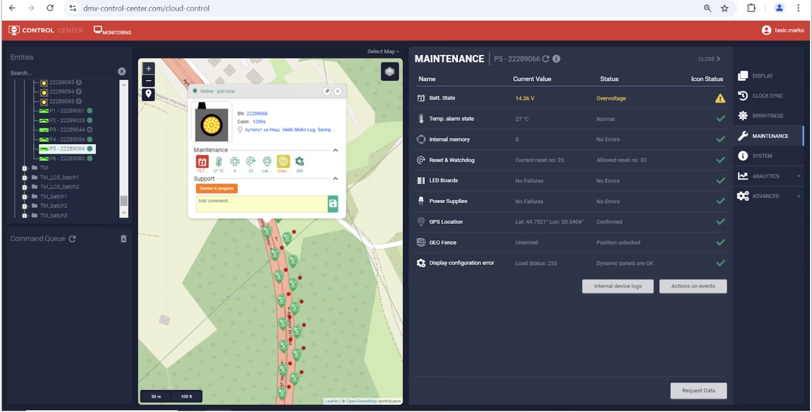
DMV Control Center management software
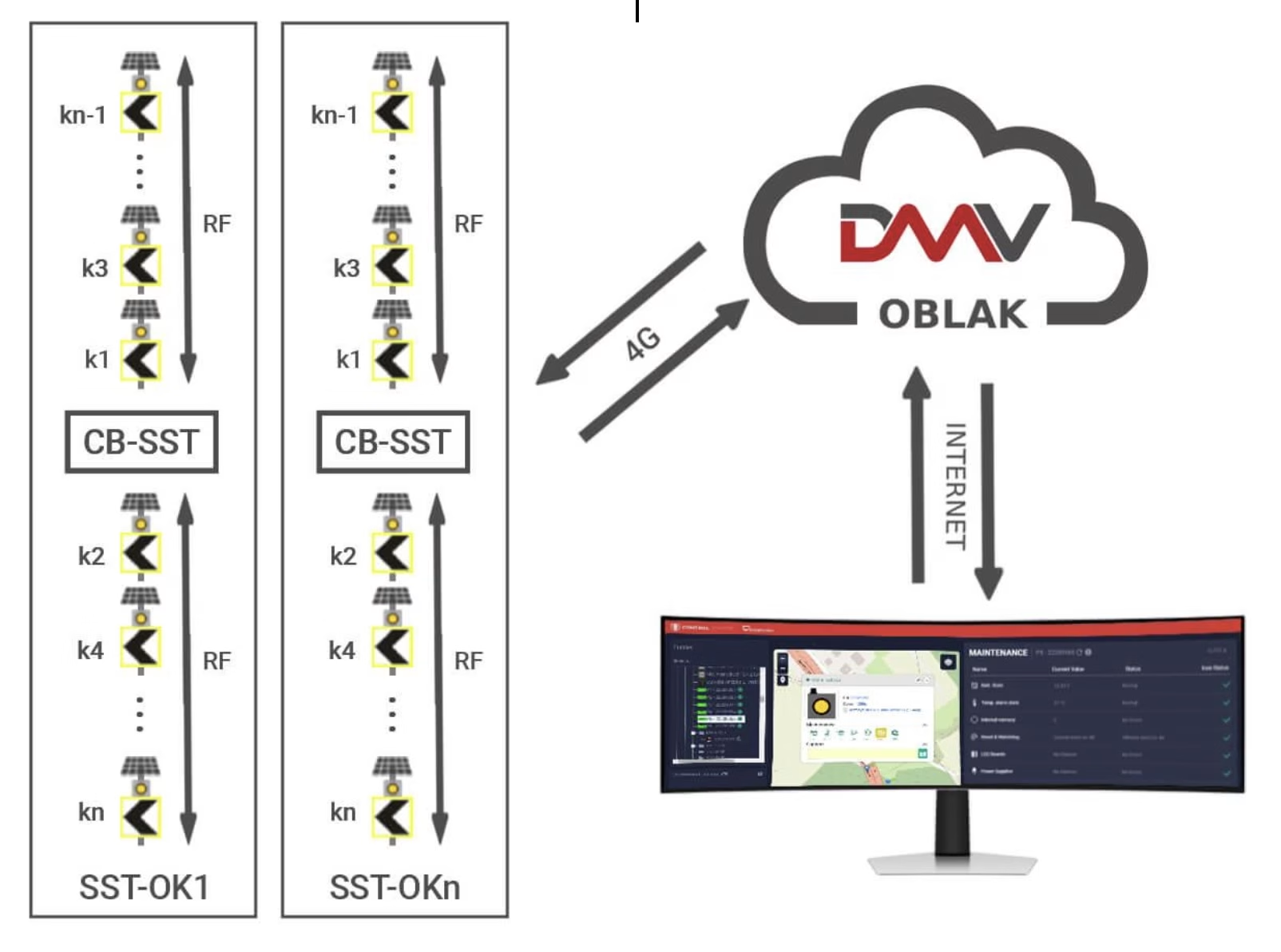
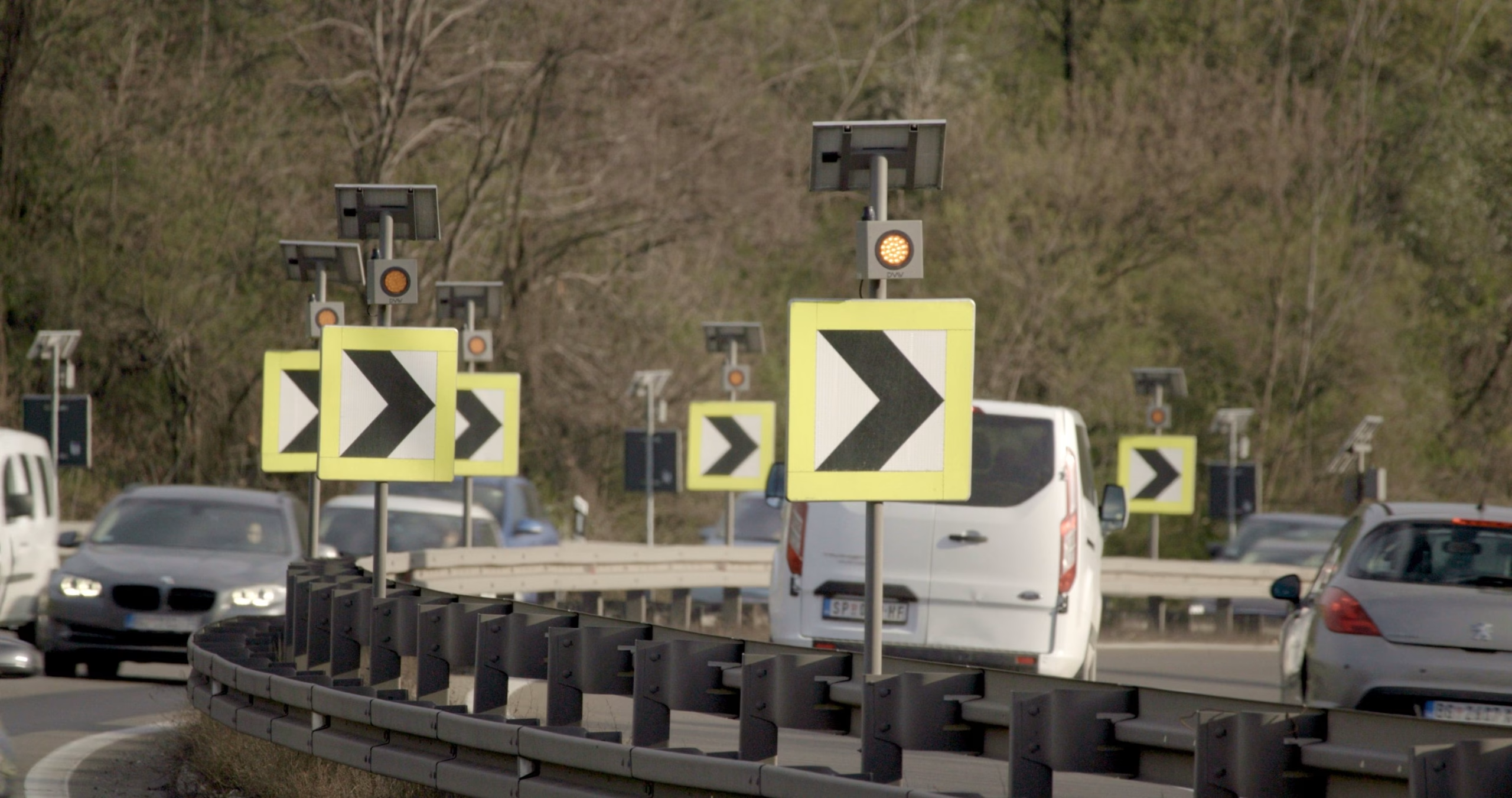
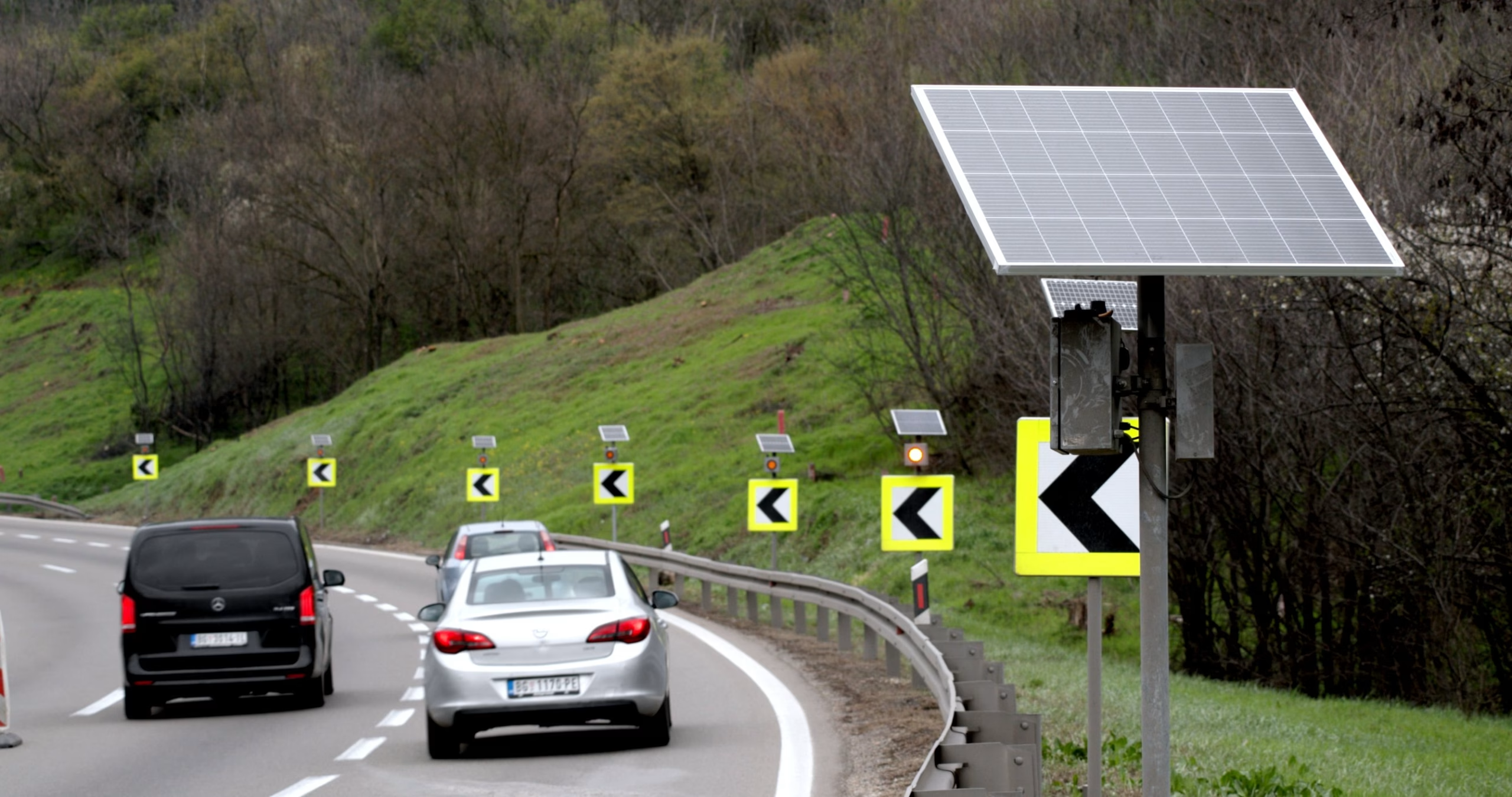
The number of signs and flashers depends on the terrain configuration and the length of the curve. The control unit must be positioned in the middle of the system, and the fleshers in front and behind the control unit must be located within a radius of up to 300m. All fleshers are connected to the system’s control unit via RF wireless communication, which manages their operation. All flashers work synchronously, with each period starting precisely at the beginning of each second (+/- 1/100 second). The control unit is equipped with a GPS receiver with PPS synchronization and synchronizes the flashers via RF.
The DMV Control Center and the control unit communicate via a 4G mobile network, enabling remote management, control, and monitoring of all system elements via the Internet. After logging into the DMV Control Center, the user will be presented with an intuitive page – a geographical map showing all the devices that make up this system in their exact locations and user can control the system, change the operating mode or collect data about the control unit itself or the flasher units.
In this way, the synchronous operation of a complex distributed system was achieved without a physical connection between the flasher and the control unit.
All system elements (control and management units and flashers) operate on solar power (12VDC).
Flashers can operate in two different modes:
SB (Synchronous Flash)
All flashers connected to the control unit turn on and off simultaneously. In this case, all flashers are controlled via one channel.
N (Sequence)
All flashers connected to the control unit turn on one after the other, creating a visual effect that aids drivers in navigating the curve. In this mode of operation, the flashers in the zone of the dangerous curve work on their own separate channel, each with its own time division in which it is active. In this operating mode, the user can insert a time section at the end of the sequence where all channels (flashers) are turned off.
Advantages of the synchronous flasher system
The main advantages of this system compared to similar ones on the market:
Synchronization Accuracy
System Autonomy
Remote Monitoring and Control
Synchronization Accuracy
The precision with which the control unit synchronizes the operation of the flashers is in the range of +/- one-hundredth of a second (10 milliseconds), which is a time that the human eye cannot recognize so that drivers see obvious synchronous light signals.
System Autonomy
The system’s autonomy is achieved by the fact that all individual components are powered by solar energy, and the communication between them is wireless. It does not require main network power, and its installation does not require expensive construction work for laying power and communication cables. Thus, the system can be placed on any section of the road regardless of the existing infrastructure.
Remote Monitoring and Control
Remote control and monitoring of all components via the DMV Control Center web portal. Through this software, the user can access the system’s control unit and change its workings, as well as check the operation of all its parts. The user can check all flashers or monitor the battery voltage level on each flasher even though these devices do not have the ability to communicate directly with the server. The control unit collects this information from all individual flashers and then forwards it to the server.
Need a customized solution?
Contact us, and together we will develop a system that fully meets your technical requirements and project conditions.